Understanding how to characterize and handle the effects of polarization in systems involving long-haul telecommunications
Understanding polarization has become a necessity in today’s fiber optic communication systems and applications. One must understand how to characterize and handle the effects of polarization in order to maximize the performances of systems involving polarization-sensitive devices. Performances of systems involving E/O modulators, optical sensors, beamsplitters interferometers, etc. can be seriously affected by polarization effects. For instance, in systems involving long-haul telecommunications the effects of the polarization mode dispersion (PMD) and polarization dependence loss (PDL) can result in very poor bit error ratios and shorter transmission distances.
One of the most important things in dealing with polarization is the alignment of the specialized polarization-maintaining (PM) fiber. PM fiber is constructed by using stress-applying parts which force the lightwave to follow a linear polarized controlled path. These parts are creating a birefringence (double refraction) into the fiber which would cause the breaking of the circular symmetry of the fiber, thus creating the two principal transmission axes within the fiber.
These axes are commonly called fast axis and slow axis (Figure 1).
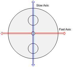
Figure 1: Slow axis and fast axis within the PM fiber.
In order to maintain a controlled linear polarization in a fiber-optic system, each component must be aligned on the desired transmission axis. The slow axis alignment is the most popular in today technology, though the manufacturers offer slow, fast and custom axis alignments (Figure 2).
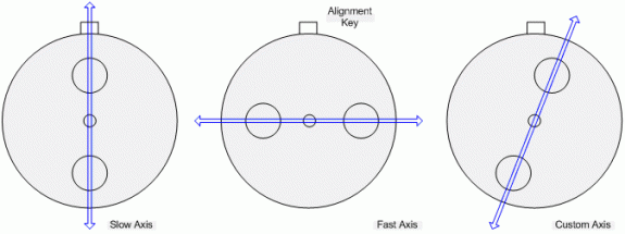
Figure 2: Different types of alignment.
The better the polarized light is launched into either the fast or slow axis, he better the polarization is maintained and controlled within the system. But what is considered a good alignment? The importance of the PM fiber alignment leads to a polarization quality alignment measurement. The polarization extinction ratio (PER) measurement would provide such a measurement. Assuming that a perfectly linear polarized lightwave is incident to a perfect fiber misaligned by an angle θ with regards to he slow axis of the fiber, the ER can be expressed as:
Figure 3: ER ≤ -10log(tan2θ)
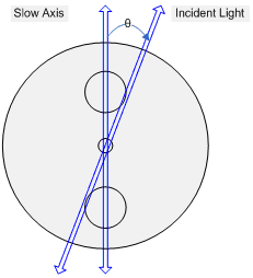
A high extinction ratio is considered to be within 20dB and 30dB. Thus to achieve an extinction ratio of 20dB, the misalignment should be less than 6° while for an extinction ratio of 30dB, the misalignment should be less than 1.8°.
There are two main aspects involving the PM alignment. The first aspect deals with the quality of alignment of the optical sources in the system. The PM launch method helps align the light relative to a principal polarization state of a PM fiber optic cable. The way the laser is launched into the fiber is crucial to the total extinction ratio of the system and its overall performances. The light source must be highly polarized in order to avoid light being transmitted into both axes,
making it impossible to predict the final polarization state of light. The second aspect deals with maintaining this polarization throughout the whole system. Manufacturers offer lasers spliced into slow, fast or custom aligned connectorized fiber. It is crucial that the connector is aligned with its key and with the system’s polarization axis.
Manufacturers offer pre-aligned (slow or fast axis) adjustable key connectors which can be in-system aligned. These connectors have a connector body which can be turned in order to obtain the highest ER possible.
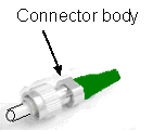
Figure 4: PM Adjustable Key Connector
Our experiences with PM aligned distributed feedback laser sources (DFB) show that in order to obtain high extinction ratios at the end of the connectorized DFB source some important details should not be ignored. First of all, the source’s extinction ratio should be over 30dB, because the connector’s misalignment will limit the final ER. In a system, the ER value will always degrade as measurements are taken further away from the source. The final ER can be any chosen measurement point from the source to the end of the optical path. Therefore, a source with an ER of 32dB with a connector ER limitation of 28dB would produce a maximum ER result of 28dB, which is a high ER value. Thus, it is impossible to obtain an ER higher than 28dB at any measurement point further down the optical path, even with rotational alignments.
Manufacturers often publish ER specifications of lightwave sources as higher than 20dB which would include the possible connector misalignment limitations.
Given the importance of the PM axis alignment across a connection, the connector selection is very important. Standard tolerances between the key and keyway of regular connectors do not allow proper angle alignment of the PM patchcords.
Our experiences with the FC angle polished connector (APC) PM fiber show that the connector choice is primordial. The main issue is that there are mainly two FC/APC standards, the narrow key and the wide key. These connectors key-width alignment do not accurately maintain the angular alignment, therefore manufacturers have produced connectors with tighter
alignment key-width specs especially for PM fiber applications.
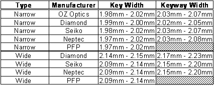
Figure 5: Key tolerances used by PM manufacturers
It is important to pay attention to the key width and keyway width specifications as these two are easily mistaken. The fact that a key fits into a keyway does not necessarily means that they are compatible. Sometimes, depending on their tolerances and wear, it’s possible to fit a wide key into a narrow keyway.
In order to achieve the highest ER measurement from a PM connectorized fiber optic system, several conditions must be met. First of all, the source light must be highly polarized and properly launched in the desired axis of the PM fiber. All over the system, the polarization of the lightwave must also be aligned with the desired transmission axis. If the PM optical path is constructed by
several segments of fiber (i.e. patchcords) joined together by optical connectors, the rotational alignment within the mating connectors and the connector choice are of the highest importance. If all these requirements are met, polarized light which travels in the desired axis can be transmitted with up to 1000 times more power than in the “wrong” axis, therefore ensuring that the polarization maintenance is good throughout the entire system.
References
“Polarization Measurements of Signals and Components”, Agilent Technologies, 2002.
“Polarization Measurements”, OZ Optics, 1999.
“8509C Lightwave Polarization Analyzer User’s/Reference Guide”, Agilent Technologies, 2001.
“ERM100 Extinction Ratio Meter Operation Manual”, Thorlabs, 2007.
“PM FC Connector Data Sheet”, Precision Fiber Products Inc.
“PM Fiber Terminations Data Sheet”, Neptec Optical Solutions Inc., 2004.
To learn more or comment: visit our site and ask for our fiber optic application engineer
This Article Copywrited 2009, PhotonCom a division of Simbol Test Systems Inc. All Rights Reserved.
